
RCA by 1977 had changed their specification to give 2.5 for the minimum magnitude of the small-signal gain at f = 1 MHz, essentially giving a minimum f T of 2.5 MHz (and 4 MHz for their MJ2955). in 1973 Philips gave f T > 0.8 MHz and f hfe > 15 kHz for their 2N3055 device). Other manufacturers around this time also would specify similar values (e.g.
How to mount an 2n3055 transistor manual#
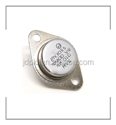
The 1967 RCA Transistor Manual, SC-13, did not mention any measure of high frequency performance for the 2N3055 by the 1971 SC-15 manual a transition frequency, f T, of at least 800 kHz was specified (at I C = 1 A) and f hfe (the frequency at which the small-signal current gain drops by 3 dB) was also specified at 1A to be 10 kHz minimum. The device is designed to operate with an efficient heatsink, but care must be taken to mount the device properly, else physical damage or worsened power handling may result, especially with cases or heatsinks that are not perfectly flat. With an "infinite" heatsink, that is: when the case temperature is certain to be 25 degrees, the power rating is about 115 W (some manufacturers specify 117 W), but most applications (and certainly when the ambient temperature is high) a significantly lower power rating would be expected, as per the manufacturer's power derating curve. The total power dissipation (written P D in most American datasheets, P tot in European ones) depends on the heatsink to which the 2N3055 is connected. Manufacturers rarely specify the V CES voltage rating for the 2N3055. Sometimes the 100 V CBO breakdown voltage (the maximum voltage between collector and base, with the emitter open, an unrealistic arrangement in practical circuits) is given as the only voltage rating, which can cause confusion. The maximum collector-to-emitter voltage for the 2N3055, like other transistors, depends on the resistance path the external circuit provides between the base and emitter of the transistor with 100 ohms a 70 volt breakdown rating, V CER, and the Collector-Emitter Sustaining voltage, V CEO(sus), is given by ON Semiconductor. The frequency at which gain begins to drop off may be much lower, see below.ĢN3055 transistor internals. It often has a transition frequency of around 3.0 MHz and 6 MHz is typical for the 2N3055A at this frequency the calculated current gain (beta) drops to 1, indicating the transistor can no longer provide useful amplification in common emitter configuration. Packaged in a TO-3 case style, it is a 15 amp, 60 volt (or more, see below), 115 watt power transistor with a β (forward current gain) of 20 to 70 at a collector current of 4 A (this may be over 100 when testing at lower currents ). And connect the power supply module to the transformer.The exact performance characteristics depend on the manufacturer and date before the move to the epitaxial base version in the mid-1970s the f T could be as low as 0.8 MHz, for example.
How to mount an 2n3055 transistor how to#
This is how to connect the amplifier module to the speaker, power supply and audio input.


The well-known power transistor pair of 2N3055 and MJ2955 used in this circuit. +/- 50V symmetrical (split/dual polarity) power supply with minimum 3A electric current should be used for maximum performance. This is 120W power amplifier schematic using TO-3 package complementary transistors, NPN and PNP polarity.


 0 kommentar(er)
